Why?
Printed circuit boards are usually produced by protecting parts of the copper layer, then etching away the unprotected parts. To selectively protect the copper, various methods can be used.
The first method exposes the photoresist on the PCB through a mask. This method is usually employed in commercial applications, as a single mask can be used to quickly expose large runs of PCBs. For hobbists, however, creating high-quality masks can be a challenge. Normally, hobbist masks are created by printing on transparencies using a laser printer. With many laser printers, the black areas have tiny holes which get transferred to the PCB, potentially breaking thin traces.
The second method, toner transfer, prints on some kind of special paper and then transfers the toner to the PCB, using the toner as an etch mask. However, as laser printers are not really designed with this application in mind, the quality of the results varies a lot between printer models.
Both methods, laser transparencies and toner transfer, are actually quite workable for PCBs with large structures (think DIP parts). Unfortunately, these days, many interesting parts come in tiny packages - think about your typical acceleromenter! Also, in space- or weight-constrained applications, like the ever more popular drones, one actually wants to use parts in the smallest packages available.
The PCBWriter project aims to make it possible to quickly and reliably create high-quality, one-of PCBs.
How does it work?
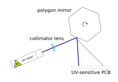
The PCBWriter essentially works like a laser printer. A laser beam is deflected by a rotating polygon mirror and thus "scanned" over a line on the PCB (see picture). The whole mirror assembly is then moved perpendicular to this line, thus writing the image line-by-line.
To create an image, rather than exposing the whole PCB, the laser needs to be modulated. An index diode near the polygon mirror allows to synchronize the modulation of the laser to the rotation of the mirror.
The mirror assembly comes from an old laser printer. However, laser printers usually use near-IR lasers, while the photoresist on PCBs is sensitive to UV light. Thus, the IR laser diode was replaced by a (much stronger) UV laser diode (~1.5W, 445nm) from eBay. The assembly for the movement of the head comes from an old flatbed scanner.
We use a STM32 microcontroller. Unlike the simpler 8 bit AVR microcontrollers (Arduino etc.), the STM32 offers vastly more peripherals (like DMA engines) and much faster execution speed. The PCB artwork is rendered to an image on the host PC, then transferred to the STM32 via USB. The STM32 generates the modulation for the laser diode from the image, controls the rotation of the mirror, and controls the movement of the PCB.
The slides from our talk in Aachen are available as PDF (in German).
Electronics
We use an STM32F4DISCOVERY evaluation board, the original polygon mirror motor driver from the printer and the original stepper motor driver from the flatbed scanner.
The laser diode driver is based on a LMH6639 opamp and an IRF530N MOSFET. It can modulate a current of ~1A at ~1MHz.
